If you are reading this article, you have most likely read through at least some of our articles about the SPARK methodology of EV conversions, and we appreciate you for that! But it is about time to move on to the final step of an EV conversion, the Kickoff phase.
So what are we “kicking off”, exactly? The project has already started from the moment you went through the Select phase making your Engineering Decisions and selecting a donor vehicle, Plan phase defining your Energy Blueprint, Architect phase outlining your Component Strategy, Route phase drawing your Integration Map, and now it’s time to define your Operational Readiness Profile in this Kickoff phase.
Your EV conversion is closer to reality, from definition to assembly, and now that it’s all put together, we have to make sure that it is WELL put together. No one wants to go through a complicated design and build process just to find out that the conversion will break down a few miles into your maiden voyage. But, how do we make sure the build was successful? What does successful even mean in this context? We are about to find out.
Validation – confirming your EV conversion build
Validation is a common term in the OEM world – it means conducting testing to confirm that the vehicle, system or component meets the objective it was designed to fulfil. In other words, they make sure it works the way it should before selling it. You will be conducting validation to make sure your EV conversion does what you designed it to do.
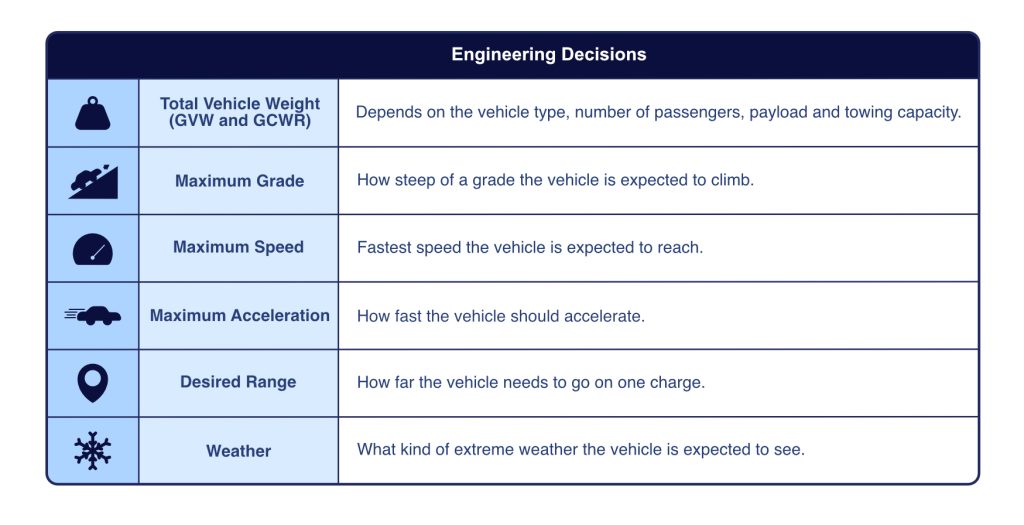
We have to categorize your validation efforts into two main activities: Basic Checkouts and Engineering Checkouts. The former is a safety checkout where you will make sure that your vehicle is safe to drive and that you have full control of it. The latter is a process to validate that your EV conversion meets the requirements outlined in your Engineering Decisions.
Basic Checkouts
Before we talk about the specific checkouts, a note of caution. Bolded and underlined to highlight its importance:
All Basic Checkouts MUST be performed with at least another person helping (this is called the Buddy System) and with wheels off the ground to avoid the vehicle potentially jolting forwards or backwards.
Please stay alive, safe and healthy when doing all of these checks. It is imperative to follow safety protocols and common sense. Never work alone when dealing with High Voltage systems. Never. Even if you are experienced.
HV wiring checkout
The High Voltage system is, obviously, critical for your EV conversion, both in terms of it’s performance (wouldn’t work without one, eh?) and safety.
According to the SAE (Society of Automotive Engineering), anything above 60V DC or 30V AC in an automotive application is considered High Voltage. This triggers a lot of different requirements in the industry, for example: any system above 60V DC needs special High Voltage connectors, special safety interlocks, PPE (Personal Protective Equipment) and specific training for technicians, color coding on cables and connectors, among other things.
Even though some EV conversions are not considered High Voltage according to this specification, for example 48V or even 24V conversions, in the context of our Basic Checkouts, the higher voltage system will be considered HV (in this example, our 48V system will be HV, our common 12V system will be Low Voltage).
All HV wiring needs to be visually checked to confirm there are no worn out cables, broken or uncovered connectors, or flat-out missing cables. Wiring also needs to be verified to have been connected correctly according to your Integration Map, and a multimeter needs to be used to confirm continuity and voltage in the proper places.
Isolation is yet another important aspect of an EV, particularly a DIY conversion, so special multimeters must be used to guarantee proper isolation between the HV circuitry and the chassis, cabin, and even other LV systems.
LV wiring checkout
Most automotive electrical systems run on 12V: engine starter, radio, blower fan, power windows, heated seats, you name it, it most likely runs on 12V.
Some systems in your EV conversion will be kept in place from the donor vehicle, things like lights, powered windows/locks, radios, cluster gauges, among other things. But some others will have to be added or modified.
Make sure all your Auxiliary Systems, discussed in the Architect Phase, are checked out. Things like brake vacuum pumps, DC-DC converters, steering assist systems, cooling systems. These all have to be checked to have power and appropriate functionality. Do the pumps run when commanded? Will they stop when expected? Does the DC-DC converter charge the 12V battery at the proper voltage? Fans operate properly?
The specific checks your conversion requires will depend on the components you have selected (Component Strategy) and how they are connected (Integration Map).
Contactor Control
This is super important to verify with at least another person in the garage, and with wheels off the ground.
Contactors are the main switch that connects the battery to the rest of the HV bus. Their operation is critical to the safety and proper functionality of the electric powertrain, so validating their operation before attempting to put wheels on the ground is necessary.
The first thing you need to confirm is that the contactors follow commands: do they close when commanded to? Do they open when commanded to?
The next thing to verify is that they properly isolate the battery from the rest of the HV bus. This can be done in many ways, for example, voltage can be checked at the input terminals of the motor controller with contactors open. No voltage should be expected when they are open, and battery voltage should be expected when closed.
Another thing to verify is that the Emergency Stop switch (which should be installed in every DIY EV conversion) properly opens the contactors, even under load. A quick test is to close contactors, and while making the electric motor spin via the accelerator pedal, actuating the Emergency Stop, or E-stop, expecting contactors to open and torque to the wheels to stop.
Torque Control
Simple enough, the idea of a Torque Control check is to verify that the motor follows the accelerator pedal commands: pedal is actuated – torque at the wheels. Pedal is released – no torque at the wheels.
Do not put wheels to the ground until all checks are passed safely. Modify or fix whatever needs fixing until everything passes and you are 100% certain that your build is safe to lower on to the ground. Once wheels are grounded, the fun starts: your first drive.
Engineering Checkouts
The first drive of any build is an interesting feeling: pride, fear, anticipation. Enjoy those feelings; even though these validation efforts are necessary, the main objective is to enjoy the build!
Now that your conversion passed the Basic Checkouts, it’s time to make sure that your EV conversion will perform as expected. Remember your Engineering Decisions? You will need to.
Total vehicle weight
One of the most critical decisions you made in the Select phase was payload. This means how many passengers, how much luggage, towing, or anything that affects how much the vehicle weighs. Back then it was an estimation: you wouldn’t be able to predict the weight of the batteries, motor, controller, etcetera. Now it’s time to weigh the vehicle.
It’s time to weigh your conversion! There are specialized shops, mainly for racing, that have 4-corner weight scales, which would be ideal to determine weight balance. How far off from your estimates is the conversion? This can help you get an idea of how much the performance of the build will differ from expectations: if the vehicle weighs more, acceleration, grade and speed might suffer. If it weighs less, then it’s the other way around.
Maximum grade
Time to take it for a spin! Go to the steepest hill you have nearby and see if the acceleration and speed performance going up the grade is acceptable to you. Make sure the hill is within range!
Maximum speed
This is a tricky one. If our designed maximum speed exceeds legal limits, DO NOT TEST ON PUBLIC ROADS. If it is within the limits, then by all means, do it safely.
Maximum acceleration
Make sure you are doing this test on a safe space. Never do it in crowded areas or high traffic roads. Always follow law and regulations.
Grab a chronometer or some sort of tool to measure 0 to 60 time. Does it match your expecations?
Desired range
Plan a short city drive and a short highway drive. See how much battery SoC (State of Charge) you use and the number of miles you cover. Even though SoC is not linear in most cases, you can extrapolate a bit to get an idea. If driving 50 highway miles used 50% of the battery, then an estimated 80 to 100 miles is your range. City driving will be a little less, so if 30 miles of city driving use 50% of the battery, then an estimated 50 to 60 miles of range is what you get.
Thermal stability
Plan 2 different drives: one short and aggressive one where there’s a lot of acceleration, braking, steep hills and the like. The other one will be a steady highway drive, preferably up a slight incline.
The idea here is to monitor temperatures of your main components: battery, motor, controller, DC/DC converter. Some components report this temperatures through software or a scan tool, some others will require thermostats that can be bought from a hardware store. Make sure your components never exceed their manufacturer-recommended temperatures under normal driving conditions. Normal driving conditions = what your Engineering Decisions call for.
Charging time and thermal stability
Charge your HV battery with the charger you selected and make sure your charging time matches what you estimated, and that the thermal stability of your OBCM, Charging Station and HV battery is achieved.
Calibration – fine-tuning your conversion’s behavior
Calibration is the process of adjusting parameters on your controller, DC/DC converter, BMS, and any other important system, in order to obtain the behavior you expect from your vehicle. Just like a “tuner” (or calibration engineer, in OEM jargon) modifies fueling, spark, and other parameters on a fuel injection system for an ICE, you will have to modify some parameters in your EV conversion to achieve your desired outcomes.
Throttle Mapping
Throttle is a word commonly used to refer to the accelerator pedal. However, a throttle is a throat, or a gullet, and it applies only to Internal Combustion Engines (ICE), since the accelerator pedal actuates a valve that allows more or less air into the combustion chamber, and with it, fuel.
An EV does not have a throttle, per se, but it’s a common term to use, so we’ll give it a partial pass. Mapping the accelerator pedal, or Throttle Mapping, is something that can be adjusted on some EV controllers, and it is basically how much torque the motor needs to generate according to the pedal position. Mapping these parameters allows for greater flexibility in terms of vehicle behavior: you can make the vehicle respond very aggressively at the slightest accelerator pedal movement, or you can make it respond slower, providing a lot more “definition” in pedal control for slow maneuvering.
Maximum/Minimum Torque Limits
The motor has a maximum and a minimum torque: it can’t make more than the maximum, or less than the minimum. But these parameters can also be “artificially” modified. For example, if the motor can have a maximum torque of 100Nm by design, but you find that so much torque is problematic, maybe breaking axles, or causing too much wheel slip, some controllers allow you to modify this limit. Say you modify it to 80Nm maximum, so when you fully depress the accelerator pedal, the motor will only give you 80Nm, not 100Nm.
Regenerative Braking Levels
Some controllers allow for regenerative braking (as discussed in the EV motor selection article of the Architect phase of SPARK) and some others even allow for various levels of ‘regen’. The idea behind varying the amount of regen is to modulate the driving experience. If there is too much regen, when you want to release the accelerator pedal (tip-outs, in OEM jargon), the vehicle will decelerate very quickly, which might be uncomfortable. Varying these levels to your liking will enhance your experience with the vehicle, hopefully making it more enjoyable.
Component Temperature Limits (motor, controller, battery)
Some components are designed to work together with their controllers, and some are not. Those that are designed as plug and play might have their controllers programmed for their temperature limits, allowing for better control, more longevity, and safer operation. However, if the controller used does not have temperature limits programmed, it is paramount to get these values from the manufacturer and program them in. This allows the controller to react to increases in temperature, lowering their power output to preserve them, or sending a signal to you, the driver, so you can take action as needed. Always monitor temperatures and get used to their normal values in your specific drive cycles and modes of operation!
State of Charge (SoC) limits
These limits can be set by the manufacturer of the battery cells, modules, or pack, and are mainly used for cell longevity. Both the BMS and the motor controller can use this information to lower, or completely cut, power from the battery pack to the HV systems in order to avoid over-discharge of the cells. It can also be “artificially” modified, for example, to stop charging once the overall SoC hits 80%. This can be overridden when your intention is to go on longer trips, so the system would then allow charging up to 100% SoC.
Voltage thresholds (cell, pack, controller)
Critical information for the system, voltage thresholds allow the controllers to cut operation of certain systems if under or over voltage events are detected in order to protect the occupants, and systems.
Battery Cell Balancing parameters
Some cell balancing can be fine-tuned in the BMS. The idea of cell balancing is to keep the cells safe and efficient, as internal cell resistance varies with varying SoC. You don’t want one cell at 20% SoC while the rest are at 65% SoC, this might cause over discharging of one cell, which could damage it.
Current Limits
These limits come from supplier specifications of the motor, inverter and battery pack, and must be programmed into the controllers to avoid damage.
Cooling system activation thresholds
If a cooling system is equipped, you have to decide when to actuates fans and pumps. Keep in mind that over-actuation is a thing, and it is possible that you are wasting energy by enabling these systems when they are not needed. On the other hand, if your thresholds are too high you risk damaging your components due to overheating, either immediately or on the long run. Calibration is an art!
Charging parameters
Charging curves are important to optimize energy storage and temperature stabilization of battery cells. At different SoCs, cells are more or less efficient at storing energy. Less efficiency = more heat. The more current you put through them at their most inefficient point of operation, the more heat they dissipate. You have to decide whether you can handle the heat dissipation and take the efficiency hit for the sake of charging speed, or if you want to lower current until the cells reach a more efficient point of operation. Always refer to manufacturer specifications and data for making these decisions.
Your Operational Readiness Profile (ORP)
So you’ve validated and calibrated your conversion. It’s time to decide if your expectations were met. It’s easy when they are met, you just have to enjoy it and celebrate. However, what happens when they have not been met, and your ORP “failed”?
It’s very evident that a project like this was not made for consumers. Meaning, you did not just design, build, and validate an EV conversion just to use it and call it a day. These articles are not written for this type of person. You are a tinkerer, an engineer, someone who enjoys projects. So chances are that once you build your first EV conversion, you are not satisfied. You want more power, better cooling, better wiring, more features.
The ORP is a transient idea, a temporary satisfaction you get when your ride meets your expectations, but at the same time, it is a way of quantifying what you want to do next. Enjoy these moments, building something is a matter of creativity, discipline, skill, not everyone can say they have built something like this in their lifetime.
SPARK – thoughts and conclusions
With this article we come to an end with our introductory series of EV conversion articles, where we give an overview of what it looks like, in our eyes, to convert an ICE powered vehicle into EV. This is by no means a research paper, industry standard, nor a marketing stunt to sell you something. This is an exercise in creativity, where we applied engineering knowledge, passion, and a desire to teach, for you to indulge, get your ideas going, and hopefully, get some inspiration.
This series of articles is our first full series of this blog, and through it we’ve learned and evolved our knowledge, writing, and teaching. We hope these articles serve a purpose, and we hope future articles, whether they’re part of a series or not, can spread our love for engineering and car culture in general.
As always, we’d love to hear from you, your experiences, doubts, questions or concerns. Feel free to reach out or leave a comment, and thank you!
End of Line – A story
Ah, the beauty of an assembly plant. Cars roll out by the minute, synchronized with…
PLAN – Designing an EV conversion from scratch: a SPARK walk through
Now that we’ve defined what we want this conversion to accomplish, we can start working…

Cold Trips – a story
Boring. Dark. Cold. The industrial warehouse where we sat was furnished to resemble a corporate…

Select – A SPARK walkthrough :Designing an EV conversion from scratch
Ah, EVs. Magical to some, blasphemous to others. Few topics divide the automotive world quite…

Stalls – a story
It was a chilly Pennsylvania morning. Jamie was late to work again; he forgot to…

Redemptive Voltage: 5 EV Conversions That Give Souls To Their Donors
Some cars are born with a soul. A few are rowdy and unhinged, some are…